MICHELLE FERDERBAR 1217500
Congruence of the x-ray field and beam perpendicularity is important in the clinical environment because we want to ensure reproducibility from image to image and have the ability to collimate as much as possible as per the ALARA principle. Field congruence means that the light field we see when collimating corresponds to what will actually happen and beam perpendicularity means that the central ray will come out where the cross-hairs meet. In Figure 1, we can see the collimator assembly and how a mirror is used to reflect the light that makes up the light field. This lab was conducted in x-ray room 6 and x-ray room 3, B114 of the Institute of Applied Health Sciences on the McMaster University Campus.
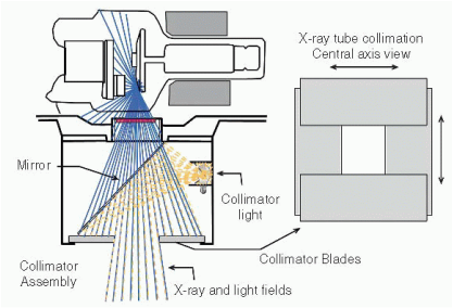
Figure 1. The x-ray tube collimator assembly is attached to the housing at the tube port, typically on a collar that allows it to be rotated. A light source, positioned at a virtual focal spot location, illuminates the field from a 45-degree angle mirror. Lead collimator blades define both the x-ray and light fields (Bushberg, 2013).
This lab involved imaging a cassette with a congruency tool and a perpendicularity tool. The perpendicularity tool featured a pair of small metal balls. It was pertinent that these were aligned to the center of the congruency tool. The film was exposed at 60 kVp and 3.2 mAs. It was repeated for each room. View the photos in the gallery below to see the set up and results. Hover over them to see descriptions.
To measure the congruency of the x-ray field, we measured the difference between the edges of the exposed rectangular field and the metal rectangle's edges or paperclips. According to H.A.R.P. and S.C. 35, this distance had to be within 2% of the SID. Our SID was set to 100 cm. Therefore, this distance was allowed to differ by up to 2 cm. For room 3, the distance was 0.30 cm. For room 6, the distance was found to be 0.2 cm. These are both clearly within acceptable standards, and is evident just by a visual check. Secondly, the dots in the center of the tool must fall within the inner circle. This circle is representative of the perpendicularity being off by less than 1.5º. Since the dots fell within the circle, we can be certain our tubes are both acceptable in terms of perpendicularity. According to S.C. 35 and H.A.R.P., the perpendicularity must be within 5%.
Reasons for misalignment in either of the above could be caused by rough handling of the tube housing, hitting the tube housing with a stretcher, mirrors shifting, if the cassette was placed in the bucky it may have not been secured, and human error when it came to setting the tube at 0 degrees (Papp, 2014). There are some issues if the beam is not perpendicular. If it is not perpendicular, images where it is highly important to have a straight beam to open up the joint spaces may fail (such as knees or even hands), whether an angle is added or not. If the light field is not congruent, tight collimation may simply be done in vain as the desired anatomy may be cut off resulting in a repeat.
References
Health Canada. (2008). Safety code 35: Safety procedures for the installation, use and
control of x-ray equipment in large medical radiological facilities.
Retrieved from http://www.hc-sc.gc.ca.
Papp, J. (2011). Quality management in the imaging sciences (4th ed.). St. Louis, Mo.: Mosby Elsevier.
Service Ontario. (2011). Healing Arts Radiation Protection Act.
Retrieved from http://www.e-laws.gov.on.ca/html/regs/english/elaws_regs_900543_e.htm.
 RSS Feed
