Chu Hui (Angela) Zeng 1152626
Spatial resolution is one of the most important characteristics that reflect the details of an image. In other words, by assessing the spatial resolution of the system, the image quality can then be monitored.
Spatial resolution refers to the ability to differentiate separate objects of high subject contrast that are adjacent to one another. Spatial frequency, another fundamental concept of radiography, is typically measured in line pairs per millimeter (lp/mm). Spatial frequency is related to spatial resolution; to be more specific, higher spatial frequency allows higher spatial resolution. As demonstrated in Figure 1, one line pair consists of the line and an inter-space of the same width as the line (Bushong, 2012). A radiograph with higher spatial resolution makes the borders of structures and small details easier to distinguish, helping to greatly improve a physician's diagnosis and/or treatment plans.
Spatial resolution refers to the ability to differentiate separate objects of high subject contrast that are adjacent to one another. Spatial frequency, another fundamental concept of radiography, is typically measured in line pairs per millimeter (lp/mm). Spatial frequency is related to spatial resolution; to be more specific, higher spatial frequency allows higher spatial resolution. As demonstrated in Figure 1, one line pair consists of the line and an inter-space of the same width as the line (Bushong, 2012). A radiograph with higher spatial resolution makes the borders of structures and small details easier to distinguish, helping to greatly improve a physician's diagnosis and/or treatment plans.
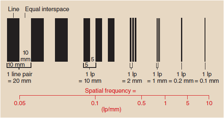
Figure 1. Spatial Frequency is Expressed in Line Pairs (Bushong, 2012).
According to the Healing Arts Radiation Protection Act (H.A.R.P.), the spatial resolution should be tested every 6 months and upon servicing of the machine, while Safety Code 35 (S.C. 35) states that the testing needs to be performed annually.
The test tool involved in this particular lab was a resolution test grid called TOR CDR. There are 30 separate groups of bar patterns on the test grid, each group comprising 5 bars and 4 spaces, giving 4½ line pairs. During the lab, this test grid was placed on a 10” x 12” CR cassette at a source-to-image distance of approximately 1 meter. The bars were angled at 45 degrees to the plate and the copper filtration was removed from the beam. The exposure was taken at 50 kVp and 2 mAs. The Kodak system was used for the reading process, and "Pattern" with raw data and no edge enhancement was selected. The same procedure and technique were then performed for DR except that the CR cassette was replaced by the DR detector, and therefore, the reading process utilizing Kodak system was eliminated. The limiting spatial resolution CR and DR labs were both conducted in X-ray room 4, B114 of the Institute of Applied Health Sciences on the McMaster University Campus.
The test tool involved in this particular lab was a resolution test grid called TOR CDR. There are 30 separate groups of bar patterns on the test grid, each group comprising 5 bars and 4 spaces, giving 4½ line pairs. During the lab, this test grid was placed on a 10” x 12” CR cassette at a source-to-image distance of approximately 1 meter. The bars were angled at 45 degrees to the plate and the copper filtration was removed from the beam. The exposure was taken at 50 kVp and 2 mAs. The Kodak system was used for the reading process, and "Pattern" with raw data and no edge enhancement was selected. The same procedure and technique were then performed for DR except that the CR cassette was replaced by the DR detector, and therefore, the reading process utilizing Kodak system was eliminated. The limiting spatial resolution CR and DR labs were both conducted in X-ray room 4, B114 of the Institute of Applied Health Sciences on the McMaster University Campus.
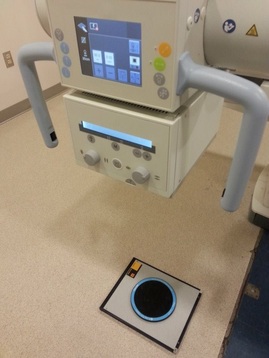 Figure 2. Determining CR Spatial Resolution. 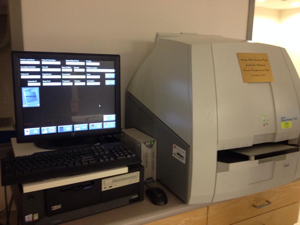 Figure 4. Kodak Reading System for CR. | 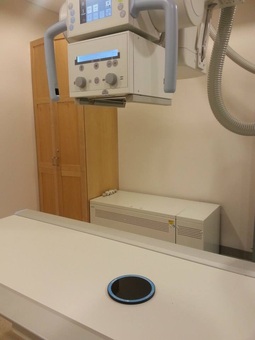 Figure 3. Determining DR Spatial Resolution. 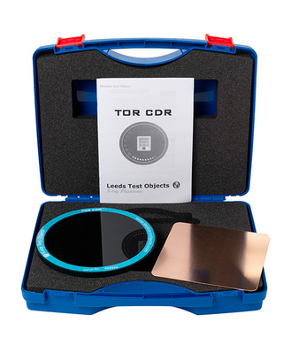 Figure 5. TOR CDR Test Grid. |
limiting spatial resolution CR
As mentioned earlier, the spatial resolution is given as the maximum number of visible line pairs per millimeter. Based on this knowledge, 14 bar groups are resolved on the CR image (Figure 6), which corresponds to a spatial frequency of 2.24 lp/mm.
Computed radiography, as an indirect digital system, requires the use of phosphorous crystals to produce an image. The finer and more closely spread the phosphor crystals are, the higher the spatial resolution will be. In the imaging plate, the crystals convert attenuated X-ray photons into light in order to produce a radiographic image. In this way, spatial resolution of a CR system would be lowered due to the occurrence of blurring caused by light. In addition, the quality of the computer screen that CR image is displayed on can affect the spatial resolution.
Computed radiography, as an indirect digital system, requires the use of phosphorous crystals to produce an image. The finer and more closely spread the phosphor crystals are, the higher the spatial resolution will be. In the imaging plate, the crystals convert attenuated X-ray photons into light in order to produce a radiographic image. In this way, spatial resolution of a CR system would be lowered due to the occurrence of blurring caused by light. In addition, the quality of the computer screen that CR image is displayed on can affect the spatial resolution.
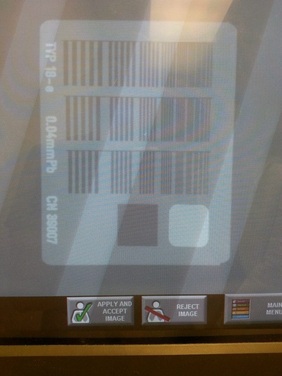
Figure 6. Spatial Resolution of CR.
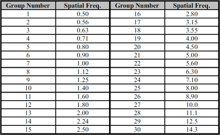
Table 1. Spatial Frequency Expressed in lp/mm.
limiting spatial resolution DR
As referred to Figure 7, 16 bar groups are able to be resolved on the DR image. According to Table 1, a spatial frequency of 2.80 lp/mm can then be determined.
Unlike CR, spatial resolution is pixel limited in DR; the size and number of pixels in the matrix are directly related to the spatial resolution that can be produced in a digital image. Therefore, the smallest resolvable object cannot be smaller than the pixel size (Bushberg, 2012). Thus, a smaller pixel size would allow the detector to capture smaller entities. Conversely, a larger number of pixels in the matrix would also create images with greater spatial resolution. Since direct-read systems do not require steps to convert the incident X-ray photons, there will not be any light involved. Therefore, no blurring due to scattered light would happen, making a direct-read digital system a superior technology in terms of spatial resolution. Also, spatial resolution of a DR system can be limited by the quality of the computer screen which displays a DR image and other deteriorating factors, such as aging.
Unlike CR, spatial resolution is pixel limited in DR; the size and number of pixels in the matrix are directly related to the spatial resolution that can be produced in a digital image. Therefore, the smallest resolvable object cannot be smaller than the pixel size (Bushberg, 2012). Thus, a smaller pixel size would allow the detector to capture smaller entities. Conversely, a larger number of pixels in the matrix would also create images with greater spatial resolution. Since direct-read systems do not require steps to convert the incident X-ray photons, there will not be any light involved. Therefore, no blurring due to scattered light would happen, making a direct-read digital system a superior technology in terms of spatial resolution. Also, spatial resolution of a DR system can be limited by the quality of the computer screen which displays a DR image and other deteriorating factors, such as aging.
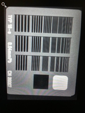
Figure 7. Spatial Resolution of DR.
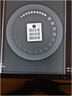
Figure 8. Leeds Test Tool Result in DR.
In conclusion, the performance of a X-ray system can be monitored by testing the limiting spatial resolution and recording the outcomes on the technique charts periodically. As a result, the testing of spatial resolution means significantly to maintain the proper functioning of radiography systems in terms of providing sufficient detailed information to help physicians make correct diagnostic and treatment decisions.
References:
Bushberg, J.T., Seibert, J.A., Leidholdt, Jr., E.M., & Boone, J.M. (2012). The essential physics of
medical imaging. (3rd ed). Philadelphia, PA: Lippincott Williams & Wilkins.
Bushong, S. (2012). Radiologic science for technologists: Physics, biology, and protection (10th ed.). St.
Louis, Mo.: Mosby/Elsevier.
Health Canada. (2008). Safety code 35: Safety procedures for the installation, use and
control of x-ray equipment in large medical radiological facilities. Retrieved March 5, 2015,
from http://www.hc-sc.gc.ca.
Leeds Test Objects Limited. (n.d.). Leeds test objects TOR CDR [PDF document]. Retrieved from
https://avenue.cllmcmaster.ca/d2l/le/content/145052/viewContent/1161504/View.
Service Ontario. (2011). Healing Arts Radiation Protection Act.
Retrieved from http://www.e-laws.gov.on.ca/html/regs/english/elaws_regs_900543_e.htm.
 RSS Feed
