Dianne guiang 1204474
When primary x-rays (x-rays leaving the tube) interact with the patient’s body, x-rays are scattered from the patient in all directions (Bushong, 2013, p.191). The scattering of the x-rays is due to an interaction called Compton scattering. This particular type of interaction results in a change in the x-ray direction and a reduction in x-ray energy (Bushong, 2013, p. 149). X-rays can be deflected in any direction but scattered photons tend to scatter in a more forward direction which means that they have a higher chance of reaching the image receptor. Scattered x-rays that reach the detector add no diagnostic value to the image. Rather, they cause the radiograph to appear gray and dull which reduces image contrast and thereby degrades image quality. To eliminate this problem, a device called a radiographic grid is used to control scatter radiation. The grid is designed to remove scatter radiation from the remnant beam (beam leaving the patient’s body) and to transmit only the remnant photons which carry useful information to the image receptor, as shown below in Figure 1. The grid is located between the patient and the image detector. Improper use of a grid however, can cause grid cutoff (which results in an underexposed radiograph) or grid artifacts such as grid lines (Papp, 2011, p. 111).
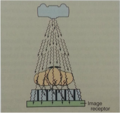
Figure 1. The only x-rays transmitted through a grid are those that travel straight in the direction of the interspace. X-rays that travel in an angle are absorbed by the radio-opaque material in the grid. Taken from Radiologic Science for technologists (10th ed.) (p. 195), by S.C. Bushong, 2013, St. Louis, MO: Mosby Elsevier. Copyright 2013 by Mosby, Inc. an affiliate of Elsevier Inc.
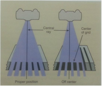 Figure 2. When a focus grid is positioned off-center, partial grid cutoff occurs over the entire image receptor. Taken from Radiologic Science for technologists (10th ed.) (p. 195), by S.C. Bushong, 2013, St. Louis, MO: Mosby Elsevier. Copyright 2013 by Mosby, Inc. an affiliate of Elsevier Inc.
 One of the most common improper grid position is when the grid is off-center where partial grid cut-off occurs over the entire image receptor which is shown in Figure 2; this results in a uniform reduction of density across the entire film. This type of grid misalignment is harder to detect on radiographs (unlike grid artifacts such as grid lines) and can lead to increased patient dose and reduced image contrast. This is the reason why grid alignment tests should be performed as part of quality control in the radiography department. According to Safety Code 35, a grid alignment test should be performed annually to check the performance of the grid.
| The purpose of this experiment was to test the alignment of the radiographic grid in the bucky mechanism with respect to the central ray of the x-ray tube. In this experiment, grid misalignment can be detected by analyzing the optical densities of the resultant dot images obtained using a grid alignment tool shown in Figure 3. | 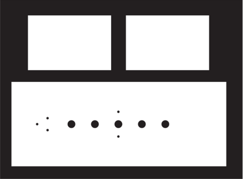 Figure 3. Grid alignment tool. Taken from Quality Management in the Imaging Sciences (p. 112), by J. Papp, 2011, St. Louis, MO: Mosby Elsevier. Copyright 2011 by Mosby, Inc. an affiliate of Elsevier Inc. |
As shown on Figure 3, the test tool contains five holes which are evenly spaced apart and three smaller holes at one end to aid in determining the tool's orientation. In this lab experiment, a moving focused grid was being used. A 400 speed 8-inch by 10-inch film-screen cassette was also used in this experiment and was placed in the bucky mechanism. It was also important to ensure that the beam was centered to the bucky; this was done with the help of the centering laser light on the x-ray tube. The grid alignment test was then performed by taking an exposure centered over each hole while the others were covered by lead strips. An exposure is also required for the three holes at the end of the test tool. Each hole was exposed using 55 kVp, 2mAs and with the x-ray tube set at a 100 cm SID to the table bucky. The film was then processed and the resulting radiograph can be seen on the slideshow below along with images of the grid alignment test process. (Hover over the images to read the image description)
As per the quality control 3H03 lab manual, if the beam is correctly aligned with the grid, the center hole will have the highest optical density and the optical density falloff pattern of the pairs of side holes will be symmetric. However, it can be seen on the last image on the slide show that the pairs of side holes on the obtained radiograph does not have a symmetrical pattern of reduced optical density. This can also be demonstrated by the table below (Table 1) which shows the recorded optical densities for each hole on the film radiograph. The table also indicates that instead of the center having the highest optical density, the fourth hole appears to be the darkest. Based on the observations and results obtained from the experiment, it can be concluded that there is suspected beam-grid misalignment.
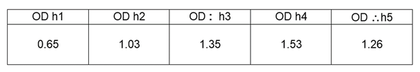
Table 1. This table shows the optical density obtained for each hole using a densitometer.
Figure 4 below illustrates a grid that is off-centered. The figure demonstrates a scenario that is similar to the results obtained in the lab where the fourth hole has the highest optical density. By looking at our results and Figure 4 below, it can be seen that since the fourth hole is the darkest, it means that the grid is off-centered towards the fourth hole. It is known that the three holes at the end of the test tool was pointing towards the x-ray room's window so, it can be concluded that the grid was off-centered towards the side of the table that is closest to the x-ray room's window. Since grid misalignment is evident based on the results from this experiment, corrective action would be needed to ensure that the beam-grid alignment is within the performance standard which is usually within ±1 inch (Papp, 2011, p.112).
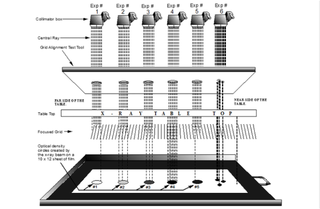
Figure 4. Results from an off-centered focused grid. Image taken from Grid Alignment Test Tool Instruction Manual by R. Tejeda, 2009.
Factors that may have caused beam-grid misalignment in a moving grid could be:
As defined by Papp (2011), grid latitude is the margin of error in centering the x-ray beam to the center of the grid before significant grid cutoff appears in the resulting image. Therefore, the beam-grid alignment must be within the grid latitude that is specified by the manufacturer (usually within 1 inch as mentioned above). The grid latitude value can be found either on the front of the grid or with the literature supplied by the manufacturer (p. 112).
- improper centering of the beam to the bucky
- misalignment of the grid within the bucky mechanism
- malfunction in the reciprocating action of the grid - the delay between initiation of grid motion and beginning of x-ray exposure may be out of sync (Fluke Biomedical Radiation Management Services, 2005)
As defined by Papp (2011), grid latitude is the margin of error in centering the x-ray beam to the center of the grid before significant grid cutoff appears in the resulting image. Therefore, the beam-grid alignment must be within the grid latitude that is specified by the manufacturer (usually within 1 inch as mentioned above). The grid latitude value can be found either on the front of the grid or with the literature supplied by the manufacturer (p. 112).
