Laura LeBlanc, 1204502
Within all medical fields, a uniform response is an essential parameter. A uniform exposure should result in a uniform response of the computed radiography imaging system – optimizing the quality of CR radiographs should be the goal of each and every radiology department. Uniformity testing in computed radiography serves two purposes: evaluating the global uniformity index and detection of artifacts on the photostimulable phosphor screen.
Uniformity of CR processing looks at each cassette’s imaging plate – fed independently in the CR reader. Imaging plates can be damaged over time due to artifacts, dust, dirt, debris and gears from reader.
Uniformity of CR processing looks at each cassette’s imaging plate – fed independently in the CR reader. Imaging plates can be damaged over time due to artifacts, dust, dirt, debris and gears from reader.
| While there are many electronic components involved with the formation, transmission and storage of an image, which are necessary to work in harmony to produce high quality images, the nonelectric components, such as the cassette and imaging plate, may be the greatest source of artifacts. Documenting the physical condition and image performance of each cassette and imaging plate on spreadsheets helps to monitor the progression of wear and may allow trends to become apparent. If trends are observed, maintenance on either the cassette or reader may prevent other cassettes and imaging plates from being affected by the maladjusted equipment. Regular cassette and image plate cleaning can also help to remove dust and dirt that degrade imaging quality. Some of the most common artifacts are white irregular lines, caused by cracks or scratches on the imaging plate; white straight lines caused by dirt on the light within the reader itself and white bright areas caused by damage to the imaging plate protective cover (Cesar et al, 2001). | 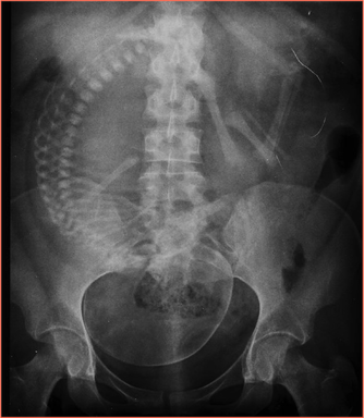 Figure 1: This x-ray is demonstrating an imaging plate artifact. As you can see in the top right corner there are scratches in the PSP imaging plate. This x-ray is of an abdomen of a 3rd trimester pregnant woman. |
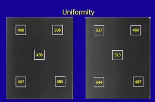
| In the lab, we took exposures at an SID of 180cm using 0.3 mm CU. An SID of 180cm was used to straighten the x-ray beam and diminish the anode-heel effect. We used 81kVp at 2mAs. The machine we were using was unable to produce 80 kVp, so we adjusted the lab to 81 kVp. To obtain a reading of 10 mR using 81 kVp, an exposure factor of 2 mAs was needed. An exposure was taken on a 10x12 cassette and processed by the care stream CR reader using the pattern setting with edge enhancement options turned off. Qualitative Assessment: The window width and level were manipulated to view the image under different levels of contrast and brightness. It was observed that at a higher brightness (4096C, 4030B) the plate disappears while at a lower brightness the plate appears the darkest (4096C, 1B). At a low contrast (2C) and low brightness (1B), there was complete darkness observed. This can be seen in the images on the right. A qualitative assessment was completed and no imaging artifacts such as creases, cracks dust or debris were seen on the image and would therefore be deemed acceptable as per AAMP Task Group standards. | The first image shows the CR reader and the setup process. The second image shows the cassette being inserted into the reader. The third image shows the highest contrast level matched with the highest brightness level showing a bright white image. As you course through the following images, the brightness is decreased and a dark square starts to appear. In the final image, the lowest contrast value (2) and lowest brightness value (1) shows a complete black square. |
According to S.C. 35, the measured noise value must be within established limits. The uniformity of the signal across the different regions of interest at the periphery and the center of the phantom must be within established limits. Images must be assessed to ensure that unacceptable artifacts are not present.
H.A.R.P. does not list any requirements for CR uniformity.
A uniformity test should be performed on each piece of equipment annually by a physicist according to AAPM.
H.A.R.P. does not list any requirements for CR uniformity.
A uniformity test should be performed on each piece of equipment annually by a physicist according to AAPM.
Quantitative Assessment:
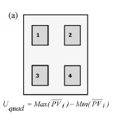
A quantitative assessment for uniformity may also be performed. In this method, the region of interest (ROI) is determined and the brightness value is determined. Then, the pixel values for 4 other ROIs on the periphery of the imaging plate were calculated. The 4 pixel values on the periphery must be within ± 10 % of brightness, up and down and side to side to the ROI. Examples of this method are shown below.
A quantitative assessment for uniformity may also be performed. In this method, the region of interest (ROI) is determined and the brightness value is determined. Then, the pixel values for 4 other ROIs on the periphery of the imaging plate were calculated. The 4 pixel values on the periphery must be within ± 10 % of brightness, up and down and side to side to the ROI. Examples of this method are shown below.
 |  |
A qualitative assessment was performed for this lab and can be seen below.
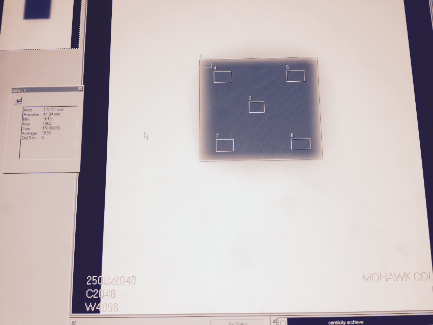 Figure 1: Shows 5 regions of interest (ROIs). | 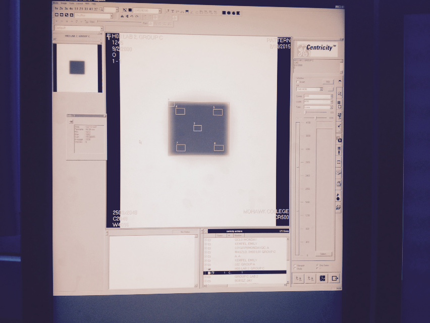 Figure 2: Shows 5 ROIs on Centricity Software. |
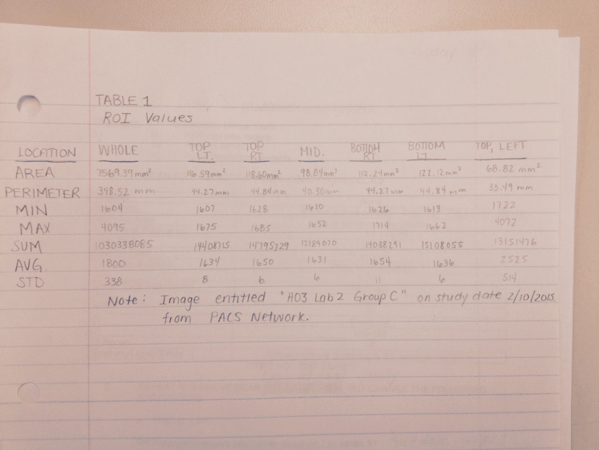
Samei et al. state that in order for the cassette to be within acceptable standards the average pixel value must be less than 20 for single screen and the exposure index standard deviation must also be less than 20. As seen in the chart above, the standard deviation for average pixel value (AVG.) are all less than 20, except for the very top left reading. This likely occurred as there was a collimation of 10x10 inches was used therefore the top reading included area of the cassette that was not directly exposed.
Papp suggests that the ROI brightness at various points throughout the image (top left, top right, bottom left and bottom right) must be within ± 10% of the middle ROI value. As you can see, in Figure 1, the average pixel values (AVG. row) are within ± 10% of the middle ROI value.
Based on the qualitative acceptance criteria set out by Papp and Samei et al., we can safely say that this cassette performs within standards and does not need to be removed from circulation.
The necessity of a quality control program for computed radiography is apparent. Using cassettes that do not pass the above criteria or subpar CR reading systems can potentially have negative effects on the radiology department. Using subpar cassettes and readers can lead to poor image quality and misdiagnosis, which can cause many problems for the department. Therefore it is important that the program not only include cleaning of cassettes and imaging plates on a regular basis but also visually inspect the cassettes and reading system to reduce the reoccurrence of image artifacts and damages from the CR reader.
References:
Bushong, S. (2008). Radiologic science for technologists: Physics, biology, and protection (9th ed.). St.
Louis, Mo.: Mosby/Elsevier.
Gray, J. (1983). Quality control in diagnostic imaging: A quality control cookbook. Baltimore: University
Park Press.
Health Canada. (2008, January 1). Safety code 35: Safety procedures for the installation, use and
control of x-ray equipment in large medical radiological facilities. Retrieved January 22, 2015,
from http://www.hc-sc.gc.ca.
Papp, J. (2011). Quality management in the imaging sciences. St. Louis, Mo.: Mosby Elsevier.
Rampado, O., Isoardi, P., & Ropolo, R. (2006). Quantitative assessment of computed radiography quality control
parameters. Physics In Medicine And Biology, 51(6), 1577-1593. doi:10.1088/0031-9155/51/6/015.
Service Ontario. (2011). Healing Arts Radiation Protection Act. Retrieved from http://www.e-
laws.gov.on.ca/html/regs/english/elaws_regs_900543_e.htm.
 RSS Feed
